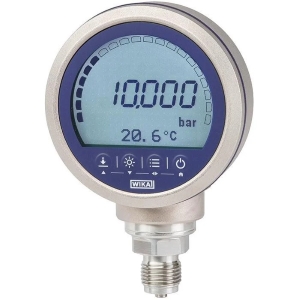
716.11 & 736.11
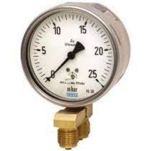
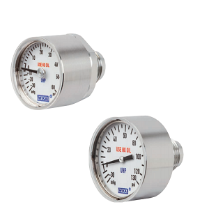
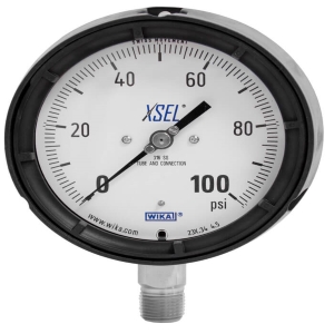
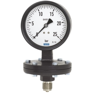
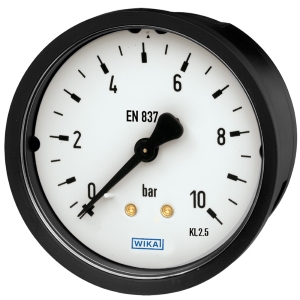
WIKA 716.11 & 736.11 – (Diffenrental Pressure Gauge) WIKA/Germany
Applications
- Differential pressure measurement at measuring points with very low differential pressures, for gaseous, dry, clean, oil and grease free media
- Model 736.11 also for aggressive media and ambience
- Filter monitoring in ventilation and heating systems
- Filter monitoring in overpressure and clean rooms
- Differential pressure controlled monitoring of ventilator and blast pressures
Special Features
- Differential pressure measuring ranges from 0 … 2.5 mbar
- As a standard zero adjustment in front
- Ingress protection IP66
- Case from stainless steel
WIKA 716.11 & 736.11
| Design | For very low differential pressures, DT – GM 87 10 226 |
| Nominal size in mm | 100, 160 |
| Accuracy class | 1.6 |
| Scale ranges | Model 716.11: NS 100: 0 … 10 to 0 … 250 mbar
NS 160: 0 … 6 to 0 … 250 mbar Model 736.11: NS 100: 0 … 25 to 0 … 250 mbar NS 160: 0 … 2.5 to 0 … 250 mbar or all other equivalent vacuum or combined pressure and vacuum ranges |
| Pressure limitation | Steady: Full scale value
Fluctuating: 0.9 x full scale value |
| Permissible temperature | Ambient: -20 … +60 °C
Medium: +70 °C maximum |
| Temperature effect | When the temperature of the measuring system deviates from the reference temperature (+20 °C): max. ±0.5 % / 10 K of full scale value |
| Process connection | Model 716.11: Copper alloy
Model 736.11: Stainless steel Lower mount (radial), parallel in line 2 x G ½ B (male), SW 22 |
| Pressure element | Model 716.11: Copper alloy
Model 736.11: Stainless steel |
| Movement | Model 716.11: Copper alloy
Model 736.11: Stainless steel |
| Dial | Aluminium, white, black lettering |
| Pointer | Aluminium, black |
| Case | Stainless steel, pressure retaining With blow-out device PUR |
| Window | Clear non-splintering plastic |
| Ingress protection per IEC/EN 60529 | IP66 |
| Options | ■ Other process connection
■ Sealings (model 910.17, see data sheet AC 09.08) ■ Panel or surface mounting flange ■ Mounting bracket for wall or pipe mounting (model 910.16, see data sheet AC 09.07) ■ Valve manifolds (models IV3x, IV5x, see data sheet AC 09.23) ■ Back mount ■ Overload safety – ⊕ side with scale ranges 0 … 2.5 mbar to 0 … 25 mbar: 3 x full scale value ≥ 0 … 40 mbar: To maximum working pressure – ⊖ side: On request |

 Tiếng Việt