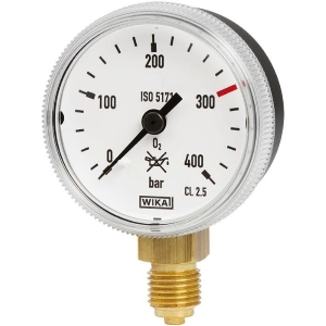
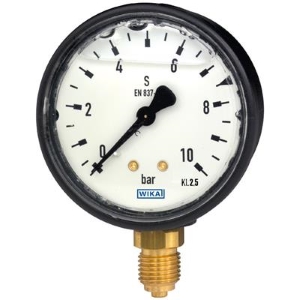
WIKA 422.12 & 423.12
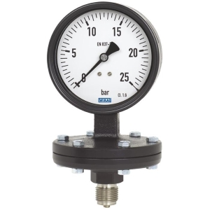
WIKA 422.12 & 423.12 – Diaphragm Pressure Gauge – WIKA/Germany
- For measuring points with increased overload
- The model 423.12 with liquid-filled case is suitable for high dynamic pressure loads and vibrations
- For gaseous and liquid media
- For mining, environmental technology, machine building and general plant construction
- With the open connecting flange option also for contaminated and viscous media
- Compatible with switch contacts
- Threaded or open flange process connection
- Scale ranges from 0 … 16 mbar
Description
Diaphragm pressure gauges are preferably used for low pressure ranges. Through the large working surface of the circular, corrugated diaphragm element, small pressure ranges can be measured reliably.
The diaphragm pressure gauges are manufactured in accordance with EN 837-3. The robust design is particularly suitable for applications in machine building, plant construction and in the water and wastewater industry.
The upper measuring flange with case and the lower measuring flange are made from one cast part, respectively.
The instrument is used for the measurement of gaseous and liquid media that will not attack cast steel.
For the measurement of highly viscous, crystallising or contaminated media, the use of an open connecting flange is recommended. The open connecting flange has the advantage over a threaded connection that the pressure port cannot become blocked. With an additional flushing connection on the open connecting flange, the pressure chamber can be easily cleaned.
Measuring systems with diaphragm elements, on the grounds of their design, offer good protection from overload, since the diaphragm can support itself against the upper flange. As standard, the diaphragm pressure gauges already feature an overload safety of 3 times the full scale value. Optionally, higher overload safeties can be realised.
WIKA 422.12 & 423.12
| Design | EN 837-3 |
| Nominal size in mm | 100, 160 |
| Accuracy class | Model 422.12: 1.6
Model 423.12: 2.5 (option 1.6) |
| Scale ranges | 0 … 16 mbar to 0 … 250 mbar (flange Ø 160 mm)
0 … 400 mbar to 0 … 40 bar (flange Ø 100 mm) or all other equivalent vacuum or combined pressure and vacuum ranges |
| Pressure limitation | Steady: Full scale value
Fluctuating: 0.9 x full scale value |
| Permissible temperature | Ambient: -20 … +60 °C
Medium: +100 °C maximum Storage: -40 … +70 °C (scale ranges ≤ 60 mbar: -20 … +70 °C) |
| Temperature effect | When the temperature of the measuring system deviates from the reference temperature (+20 °C): max. ±0.3 %/10 K of the span |
| Process connection | Steel, lower mount, G ½ B (male), SW 27 |
| Pressure element | ≤ 2.5 bar: Stainless steel 1.4571
> 2.5 bar: Stainless steel 1.4568 |
| Movement | Copper alloy, wear parts argentan |
| Dial | Aluminium, white, black lettering |
Pointer |
Aluminium, black |
| Case | Grey cast iron, black |
| Window |
Instrument glass |
| Options | ■ Other process connection
■ Sealings (model 910.17, see data sheet AC 09.08) ■ Wetted parts from stainless steel, pressure chamber sealing from FPM/FKM (model 432.12) ■ Overload safety: 10 x full scale value, max. 40 bar ■ Vacuum safe to -1 bar ■ Open connecting flanges per DIN/ASME from DN 15 to DN 80 (preferred nominal widths DN 25 and 50 or DN 1″ and 2″ per data sheet IN 00.10) ■ Pressure element > 2.5 bar: Stainless steel alloy (Inconel) ■ Switch contacts (see data sheet AC 08.01) |
| Ingress protection per IEC/EN 60529 | Model 422.12: IP54
Model 423.12: IP65 (with liquid filling) |

 Tiếng Việt
