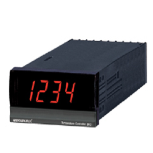
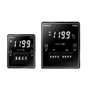
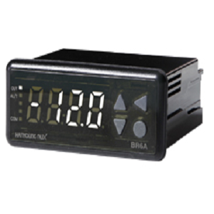
– 0.5 % high accuracy indicator
– Simple exclusive indication
– Power voltage 110/220 V a.c
– Character height 14.2/20.0 ㎜ LED applied
Suffix code
| Model | Code | Content |
| BK3- | Digital Temperature Indicator | |
| Input type | K | K thermocouple (refer to the range and input code chart) |
| K1 | ||
| J | J thermocouple (refer to the range and input code chart)) |
|
| P1 | Resistance Temperature Detector(RTD) Pt100 Ω (refer to the range and input code chart) |
|
| P2 |
· Specification
| Input sensor |
hermocouple | K, J (ITS-90) |
| RTD | Pt100 Ω (IEC) | |
| Input sampling time | 100 ㎳ | |
| Input display resolution | Usually less than indication value 1 ℃ (0.1 ℃) | |
| Input impedance | 1 ㏁ (thermocouple) | |
| Allowable wiring resistance |
Within 10 Ω of each 3 wires (but resistances among 3 wires should be same) |
|
| Allowable input voltage | Within ±2.5 V d.c. (thermocouple, RTD) | |
| Display accuracy | ±0.5 % of FS ±1 Digit | |
| Insulation resistance | 20 MΩ min (500 V d.c.) | |
| Dielectric strength | 3,000 V a.c. 50/60 ㎐ for 1 minute (Between the primary terminal and the secondary terminal) |
|
| Power Supply Voltage | 100 – 240 V a.c. 50/60 ㎐ | |
| Voltage fluctuation | ±10 % of power supply voltage | |
| Power consumption | 3 VA max | |
| Ambient temperature | 0 ~ 50 ℃ | |
| Storage temperature | -25 ~ 65 ℃ | |
| Vibration resistance | 10 – 50 ㎐, Peak amplitude for 2 hrs each in X, Y and Z direction |
|
| Shock resistance | 300 ㎨ each in X, Y and Z direction for 3 times | |
| Weight | 180 g | |
| [ Range and input code chart ] |
| Classification | Code | Input | Range (℃) |
| Thermocouple | K | K Thermocouple | 0 ~ 1,300 ℃ |
| K1 | 0.0 ~ 199.9 ℃ | ||
| J | J Thermocouple | 0 ~ 400 ℃ | |
| RTD | P1 | Pt100 Ω | – 199 ~ 600 ℃ |
| P2 | – 199.9 ~ 199.9 ℃ |

 English