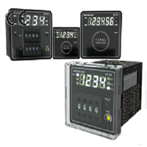
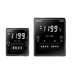
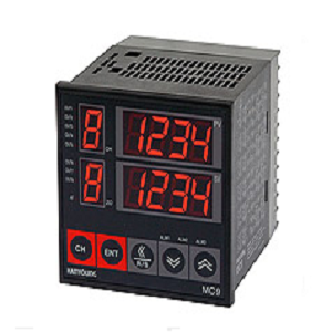
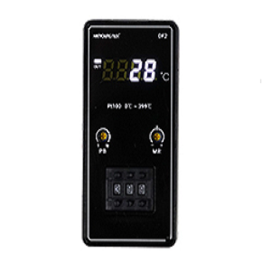
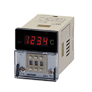
– High brightness white LED applied,
and improved visibility by indication in white color.
– Easy input/output status check by white lamp
(reset input/prohibition input/Time value indication/output indication)
– Easy maintenance in a state of terminal wiring by separate structure.
(plug-in terminal structure case applied)
– Space efficient from short body.
(80mm(GF4A), 75mm(GF7A) depth of the rear part in condition of panel attachment)
– Improved durability and design by applying acrylic window on the front part.
– Protection cover for the front part, and for terminal block on the rear part.(optional)
– Easy-to-set thumbwheel switch applied.
– Addition/substraction, Blackout compensation/power reset,
and voltage input/no-voltage input with deep switch on the side part
– Decimal position, counter/timer function selection,
and on-delay/off-delay selection of control output available.
– Power supply voltage : 100 – 240 V a.c. 50/60 Hz
– Prescaling function.(GF7)
– Blackout compensation : 10 years (using nonvolatile memory)
Suffix code
| Model | Code | Description | ||||
| GF | ⃞- | ⃞ | ⃞ | ⃞ | ⃞ | Digital counter / timer |
| Appearance | 4A | 48(W) X 48(H) ㎜ | ||||
| 7A | 72(W) X 72(H) ㎜ | |||||
| Model | P | Preset counter/timer | ||||
| T | Total counter/timer | |||||
| Display digits | 4 | 4 Digit-display (9999) | ||||
| 6 | 6 Digit-display (999999) ※ GF7A model only | |||||
| Control output | 0 | No output(Display only) | ||||
| 1 | 1-Stage output | |||||
| 2 | 2-Stage output ※ GF7A model only | |||||
| Terminal structure | T | Terminal | ||||
| S | 8 pin plug ※ GF4A model only | |||||
· Specification
| Model | GF7A | GF4A | GF4A- ⃞ ⃞ ⃞ S | ||
| Power Consumption | 100 – 240 V a.c. 50/60 Hz (Voltage fluctuation rate : ±10% | ||||
| Power Consumption | ▪ P41T(6.6VA),P42T(7.3VA) ▪ P61T(6.6VA),P62T(7.6VA) ▪ T60T(6.6VA) |
▪ P41T(6.4VA) ▪ 40T(5.6VA) |
▪ P41S(5.9VA) ▪ T40S(5.4VA) |
||
| Display method | White 7 segment LED | ||||
| Character size | ▪ P62T/P61T/T60T ▪ P42T/P41T(13.6 X 7.8㎜) |
8.5 X 5.0 ㎜ | |||
| Counting speed | 1 / 30 / 1k / 5k cps | 30 / 5k cps | |||
| Blackout compensation | 10 Years (nonvolatile memory used) | ||||
| Return time | 500ms or less | ||||
| Timer operation error | Power start : ±0.01% ±0.05seconds or less (ratio to setting value) | ||||
| Input | ▪ Input method selection by ecternal swich (voltage input/no-voltage input) ▪ Counter (composed of CP, CP2 RESET), timer(composed of INHIBIT, RESET) ▪ voltage input: HIGH level(5V – 30Vd.c.), LOW level(0V – 2Vd.c.),input resistance (about4.7kΩ)▪ NO-voltage input: Impedance in case of short cicuit(1kΩor less),residual voltage in case of short-circuit(2Vd.c.or less) |
||||
| Min. input signal time | 20ms or more(RESET, INHIBIT input) | ||||
| One-shot output time |
1st stage | 0.5 seconds fixed | – | – | |
| 2st stage | 0.05 ~ 5.8 seconds | ||||
| External power supply | 12Vd.c. 100mA max. | ||||
| Control output |
Contact | 1st stage | OUT(SPDT, 1c) | OUT(SPST, 1a) | |
| 2st stage | OUT(SPDT, 1c), OUT2(SPDT,1c) |
– | |||
| capacity | SPDT : NC(250Va.c. 2a, 250Va.c. 5A), NO(250Va.c. 5A) Resistance load |
250Va.c. 5A Resistance load | |||
| Non-contact | 1st stage | OUT(NPN Open collector) | – | ||
| 2st stage | OUT1, OUT2 (NPN 2 open collector circuits) |
– | |||
| Capacity | 30 Vd.c. 1000 ㎃ max | ||||
| Relay life | Electrical(more than 50,000 times), Mechanical(more than 10 million times) | ||||
| Insulation Resistance | 100MΩ or more(based on 500Vd.c. mega) | ||||
| Dielectric strength | 2,000Va.c.60Hz 1minute(between the conductive part terminal and the case) | ||||
| Noise resistance | Square wave noise by noise simulator±2,000V(Pulse width 1µs) | ||||
| Vibration | ▪ Durability: 10-55Hz(1minute cycle), Double amplitude 0.75㎜,X‧Y‧Z 2 hours each direction▪ Malfunction: 10-55Hz(1minute cycle), Double amplitude 0.5㎜,X‧Y‧Z 10 minutes each direction | ||||
| Ambient temperature& humidity | -10 ~ 55℃, 35 ~ 85%R.H. | ||||
| Storage temperature | -20 ~ 65℃ | ||||
| Weight(g) | ▪ P41T: 184g ▪ P42T: 190g ▪ P41T: 184g ▪ P42T: 190g ▪ P41T: 184g |
▪ P41T: 108g ▪ P40T: 100g |
▪ P41S: 92g ▪ P40S: 84g |
||

 English
