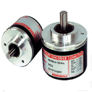
Suffix code
| Model | Code | Information | |||||
| HE | Shaft rotary encoder (Incremental) | ||||||
| Dimension | 40B | 6 | Outer diameter : Ø 40 ㎜ axis : Ø 6 ㎜ | ||||
| 8 | Outer diameter : Ø 40 ㎜ axis : Ø 8 ㎜ optional : (Option) | ||||||
| 50B | 8 | Outer diameter : Ø 50 ㎜ axis : Ø 8 ㎜ | |||||
| Number of pulse | * | Ø6 (External Dia Ø40), Ø8 (External Dia Ø50) | |||||
| Output signal | 2 | A , B phase | |||||
| 3 | A , B , Z phase | ||||||
| 3C | A , B , /Z phase | ||||||
| 4 | A , B , /A , /B phase | ||||||
| 6 | A , B , Z , /A , /B , /Z phase | ||||||
| Output circuit | N | 12 | NPN voltage output (5 – 12 V DC) | ||||
| 24 | NPN voltage output (12 – 24 V DC) | ||||||
| O | 12 | NPN open collector output (5 – 12 V DC) | |||||
| 24 | NPN open collector output (12 – 24 V DC) | ||||||
| T | 12 | Totem pole output (5 – 12 V DC) | |||||
| 24 | Totem pole output (12 – 24 V DC) | ||||||
| L | 5 | Line Driver output (5 V DC) | |||||
| 12 | Line Driver output (12 V DC)- Apply only for HE40B, HE50B | ||||||
| 24 | Line Driver output (24 V DC)- Apply only for HE40B, HE50B | ||||||
| Model | Number of pulse per 1 revolution | ||
| HE40B / HE50B |
|
| ※ A and B phase only can be generated with “*” mark (Line drive output : A, /A. B, /B phase) ※ Pulses other than pulses in the chart are order made product |
· Specification
| Mode | HE B– |
HE B– |
HE B– |
HE B– |
|||||||||||||||||||
| Output type | NPN Voltage output | NPN Open collector output | Totem Pole Output | Line Driver Output | |||||||||||||||||||
| Electrical Specification |
Output signal | A, B, Z phase | A, B, Z, /A, /B, /Z phase | ||||||||||||||||||||
| Phase difference on Output |
Phase difference between A. B phase : T/4 ± T/8(Cycle of A phase = T) | ||||||||||||||||||||||
| Max. Response Frequency |
300 kHz | ||||||||||||||||||||||
| Power voltage | 5 – 12 V d.c / 12 – 24 V d.c ± 5% | 5/12/24 V d.c ± 5% | |||||||||||||||||||||
| Current Consumption |
60 mA Max.(No – load) | ||||||||||||||||||||||
| Connection method |
WIRE | ||||||||||||||||||||||
| Control output |
|
|
|
||||||||||||||||||||
| Response Time | 1µs Max. (Cable length 2.0 m / sink = 30 mA) |
1µs Max. (Cable length 1.5 m / sink = 10 mA) |
1µs Max. (Cable length 1.5 m / sink = 30 mA) |
||||||||||||||||||||
| Mechanical Specification |
Starting Torque | Ø40 : 4 x 10⁻³ N . m Max. / Ø50 : 7 x 10⁻³ N . m Max. | |||||||||||||||||||||
| Moment of inertia | Ø40 : 4 x 10⁻⁶ kg . m2 Max. / Ø50 : 7 x 10⁻⁶ kg . m2 Max. | ||||||||||||||||||||||
| Permissible Shaft Loading |
Ø40 : Radial : Within 30N, Thrust : Within 20N / Ø50 : Radial : Within 50N, Thrust : Within 30N | ||||||||||||||||||||||
| Max. Permissible Revolution |
5000 r/min | ||||||||||||||||||||||
| Insulation Resistance | Over 100 MΩ(Base on 500 V d.c mega between terminal and case) | ||||||||||||||||||||||
| Dielectric Strength | 800 V a.c(Between terminal and case at 60 Hz for 1 minute) | ||||||||||||||||||||||
| Vibration Resistance | 10 – 55Hz(Cycle for 1 minute), Double amplitude width: 1.5mm, Each X Y Z direction for 2 hours | ||||||||||||||||||||||
| Shock Resistance | Ø40 : Max 490 ㎨, Ø50 :Max 735 ㎨ | ||||||||||||||||||||||
| Ambient Temperature | -10 ~ 70 °C(Without condensation), Storage Temperature : -25 ~ 85 °C | ||||||||||||||||||||||
| Ambient Humidity | 35 ~ 85% R.H. | ||||||||||||||||||||||
| Protection | Protection IP 50(IEC Standard) | ||||||||||||||||||||||
| Wire Specification | 5 P, Ø5.0 ㎜, length: 1.5 m, shield cable(HE40B, HE50B cable length option : 2 m, 8 m, 10 m) (Line drive type : 8P, Ø5.0 ㎜, length : 1.5 m, shield cable) |
||||||||||||||||||||||
| Weight | Ø40 : 170 g, Ø50 : 200 g | ||||||||||||||||||||||
| Accessory | Ø 40 : Ø 6.0 ㎜ / Ø 8.0 ㎜ coupling, Ø 40 : Ø 8.0 ㎜ coupling, bracket | ||||||||||||||||||||||

 English