– Digital Input (DI)
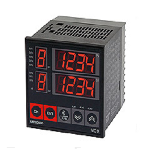
– Control 4/8 channels
– Communication function (RS232, RS485/422)
– Heating/cooling control (4 channels)
Suffix code
| [4 channel] |
| Model | Code | Description |
||||
| MC9-4 | 4Channel Digital Thermostat size : 96 (W) X 96 (H) ㎜ | |||||
| Control type | D | Cooling control (direct action) | ||||
| R | Heating control (reverse action) | |||||
| Input type | Refre to “code” of input code chart | |||||
| Output 1 ~ 4 | M | Relay contact output | ||||
| S | SSR operation output | |||||
| 4 | Current output (4 – 20 ㎃ d.c.) | |||||
| Optional | N | NONE | ||||
| 3 | AL2, AL3 + RS485/422 + contact input | |||||
| Power supply voltage | 2 | 100 – 240 V a.c. 50/60 ㎐ | ||||
| [8 channel] |
| Model | Code | Description | |||||
| MC9-8 | 8Channel Digital Thermostat size : 96 (W) X 96 (H) X 100 (D) ㎜ |
||||||
| Control type | D | Cooling control (direct action) | |||||
| R | Heating control (reverse action) | ||||||
| Input type | Refre to “code” of input code chart | ||||||
| Output 1 ~ 4 | M | Relay contact output | |||||
| S | SSR operation output | ||||||
| 4 | Current output (4 – 20 ㎃ d.c.) | ||||||
| Output 5 ~ 8 | N | None (when selected, input channels 5 ~ 8 are for indication | |||||
| M | Relay contact output | ||||||
| S | SSR operation output | ||||||
| 4 | Current output (4 – 20 ㎃ d.c.) | ||||||
| Optional | N | None (Alarm output AL1, 2, 3 installed as standard) | |||||
| 3 | RS485/422 + contact input | ||||||
| Power supply voltage | 2 | 100 – 240 V a.c. 50/60 ㎐ | |||||
| [ Sensor Input Type & Range Code ] |
| Category | Code | Input Type | Input Range(℃) | Accuracy |
| Thermocouple | K0 | K | -200 ~ 1,370 | ± (0.3 % of F.S ± 1 Digit) or ± 2 ℃ whichever is greater |
| K1 | K | -199.9~999.9 | ||
| J0 | J | -200 ~ 1200 | ||
| J1 | J | -199.9 ~ 999.9 | ||
| E0 | E | -200 ~ 900 | ||
| E1 | E | -199.9 ~ 900.0 | ||
| T0 | T | -199.9 ~ 400.0 | ||
| R0 | R | 0 ~ 1700 | ||
| R1 | R | 0.0 ~ 999.9 | ||
| B0 | B | 100 ~ 1800 | ||
| B1 | B | 100.0 ~ 999.9 | ||
| S0 | S | 0 ~ 1700 | ||
| S1 | S | 0.0 ~ 999.9 | ||
| L0 | L | -199.9 ~ 900.0 | ||
| N0 | N | -200 ~ 1300 | ||
| N1 | N | -199.9 ~ 999.9 | ||
| U0 | U | -199.9 ~ 400.0 | ||
| W0 | W | 0 ~ 2300 | ||
| A0 | PL2 | 0 ~ 1390 | ||
| RTD | P0 | Kpt100 Ω | -199.9 ~ 500.0 | ± (0.3 % of F.S ± 1 Digit) or ± 0.8 ℃ whichever is greater |
| D0 | Pt100 Ω | -199.9 ~ 600.0 | ||
| Direct current | V0 | 0 – 5 V | -199.9 ~ 999.9 | ± (0.3 % of F.S ± 1 Digit) |
| V1 | 1 – 5 V | -199.9 ~ 999.9 | ||
| V2 | 0 – 10 V | -199.9 ~ 999.9 |
· Specification
| Model | MC9 | ||||||
| W × H × D (mm) | 96 × 96 × 100 | ||||||
| Function |
|
||||||
| Power Voltage | 110 – 220 V a.c (50 – 60 ㎐) | ||||||
| Power consumption | 100 V a.c (below 14 VA) / 240 V a.c (below 20 VA) | ||||||
| Input |
|
||||||
| Output | Type (Relay Output, Voltage Pulse Output, Triac Output, 4 – 20 ㎃ Output, 0 – 20 ㎃ Output) | ||||||
| Alarm | 1a Contact Type / 250 V AC, 1 A (for resistive load) / Life time: above 300,000 times ON/OFF | ||||||
| Communication |
|
||||||
| Contact input | From Below 2㏀ ON, From Above 15 ㏀, OFF | ||||||
| Operating Environment |
|

 English