Suffix code
| Model | Code | Description | ||||
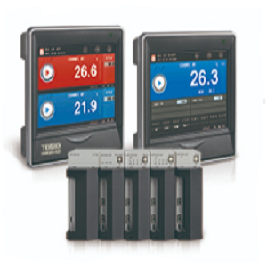
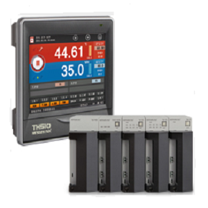
| TD51 | Programmable temperature controller | |||||
| Display | 0 | 2-channel | ||||
| 1 | 1-channel | |||||
| Display | 1 | display(5.7″ TFT LCD) | ||||
| N | None | |||||
| Input/output | 1 | 8 input points/6 output points(1 module)+Power module+Control module | ||||
| 2 | 8 input points/14 output points(2 modules)+Power module+Control module | |||||
| 3 | 16 input points/16 output points(3 modules)+Power module+Control module | |||||
| N | No input/output | |||||
| Language | S | Korean, English, and Chinese(Simplified) | ||||
| ※ This product consists of the display and control(power, control, input, and output modules). |
| (Up to 32 contact input/output points, respectively) |
| [Components] |
| Product | Model | Description |
| Display | TD510-1N |
Display |
| Control module | TD510-MAIN | Temperature 2-channel control module |
| TD510-MAIN | Temperature 1-channel control module | |
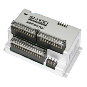
| Power module | TM-PWR | Power module |
| Input module | TM-DI | Module with 16 input points |
| Output module | TM-DO | Module with 8 output points |
| Input/output module | TM-DIO | Module with 8 input and 6 output points |
· Specification
| [Sensor input] |
| Input type | 2 types of thermoresistor (Pt-100, KPt-100), 11 types of thermocouple (K, J, E, T, R, B, S, L, N, U, Wire 5-26) 4 types of DC voltage (-10 – 20 mV, 0 – 100 mV, 1 – 5 V, 0 – 30 V) |
| Sampling cycle | 250 ms |
| Measured current of thermoresistor(RTD) | Approx. 0.21 mA |
| Input resistance | Thermocouple : 1 ㏁ or more; DC voltage : 1 ㏁ or more |
| Allowable wire resistance | Thermoresistor : Max. 100 Ω/wire (For RTD between -100.00 and 150.00, max. 10 Ω/wire) Thermocouple : 200 Ω or less DC voltage : 2 ㏀ or less |
| Influence of wire resistance | Thermoresistor : ±0.3 ℃/10 Ω (3 wires must have the same wire resistance) |
| Allowable input voltage | Thermocouple : ±10 V d.c. or less, DC voltage : ±33 V d.c. or less |
| Error of reference junction contact(RJC) temperature | ±1.5 ℃ (0 ~ 50 ℃) |
| Detection of sensor disconnection(Burn-out) | UP-Scale for disconnection |
| [Performance] |
| Display accuracy |
|
|||||
| Insulation Resistance | 20 ㏁ or 500 V dc between power supply terminal and FG terminal. | |||||
| Internal voltage |
|
| [General Specifications] |
| Power voltage | 100 – 240 V a.c. | ||
| Voltage fluctuation rate | ± 10% of supply voltage | ||
| Power Consumption | 30 VA max | ||
| Ambient temperature | 0 ~ 50 ℃ | ||
| Ambient humidity | 20 ~ 90 % RH (However, no condensation ) | ||
| Storage temperature | -25℃ ~ 70℃ | ||
| Internal vibration | 10 – 55 Hz, amplitude 0.75 mm, 4 directions in 3 directions, 5 minutes / cycle | ||
| Internal shock | 147 m/s², 3 times in 3 directions | ||
| Dimensions |
|
||
| weight | 132 Kg |
| [Control function] |
| Input | Input calibration(Sensor bias) | EUS (0 ~ 100%) | ||
| Scaling(Scaling) | DC voltage(VDC) : Input scaling according to conversion range | |||
| Input filter(LPF) | 0 – 120 S | |||
| Control output | control output |
|
||
| Control operation | operating mode | Program control, device control selection | ||
| Pattern | 100 patterns(1 pattern/100 segments) | |||
| Segment | 2000 segments | |||
| PID group | 4 groups per channel (Level PID) | |||
| Auto tuning | Auto tuning according to target setting value | |||
| Proportional band | 0.00 – 100.00 % (For 0.00 %, ON/OFF control) | |||
| Integral time | 0.0 – 3,000 S (OFF when 0 S) | |||
| Derivative time | ||||
| ON/OFF control | Set 0.0 to proportional band(PB) | |||
| Normal Open/Normal Close | According to selection of Normal Open/Normal Close for control output | |||
| Control mode | Heating Control / Cooling Control | |||
| Control method | Channel unused, simultaneous channel operation, individual channel operation selection | |||
| Hysteresis | EUS (0 ~ 100 %) | |||
| Transmission output | Temperatre(Ch.1 and 2) | 4 – 20 mA d.c. Specific value(PV), Setting value(SV) and Output(MV) |
||
| Scaling | Auto scaling for defined upper/lower limit range(4 – 20 mA d.c.) | |||
| Alarm setting | Alarm setting | System alarm : 8 points Assign 4 of 8 pattern alarms to a pattern |
||
| Alarm type | Absolute upper/lower limit, Offset upper/lower limit, and Within/Out of range | |||
| Absolute alarm setting range | EU (0 ~ 100 %) | |||
| Offset information setting range | EUS (-100 ~ 100 %) | |||
| Hysteresis | EUS (0 ~ 100 %) | |||
| Memory specifications | Internal memory | Non-volatile memory : 80 MB – Saving of 15 days at 1 S interval | ||
| External memory | SD card(4 GB) : Saving of 2 year at 1 S interval | |||
| Saving interval | 1 ~ 360 | |||
| Memory information | Program information, setting value, recovery, and temperature setting/specific/output value |
| [Display specifications] |
| Display | TFT color LCD (115.2 X 86.4 mm : 5.7″) |
| Number of Pixels | 640 X 480 Pixel |
| Back light | LED Back light |
| Life cycle of back light | Approx. 40,000 h |
| Touch type | Resistive type (4 Wires) |
| Language | Korean/English/Chinese(Simplified) |
| [Output specifications] |
| Contact output(DO) | Up to 32 relay | A Contact | 30 V d.c. 3 A max, 250 V a.c. 3 A |
| B Contact | NO : 30 V d.c. 5 A max. 250 V a.c. 5 A | ||
| Control output | SSR output | ON : 18 V d.c. Pulse voltage(800 Ω or more load resistance) | |
| SCR output | 4 – 20 mA d.c. (600 Ω or less load resistance) | ||
| Relay output | 30V d.c. 3A max, 250V a.c. 3A | ||
| Transmission output | Current output | 4 – 20 ㎃ d.c | |
| Load resistance | 600 Ω or less load resistance | ||
| Output limit | -5.00 ~ 105.00 % | ||
| Output type | Specific value(PV), Setting value(SV), Output(MV), and random | ||
| Refresh interval | 250 ㎳ | ||
| [Contact input] |
| Max. number of input | 32 points |
| Input type | No-voltage contact input |
| Operational conditions | During operation/Always |
| [Communication specifications] |
| Applied standard | RS485 |
| Max. connection number | 1:32 (address 1 – 99) |
| Communication type | 2-wire |
| Synchronization | Asynchronous |
| Communication distance | Approx. 1.2 km or less |
| Communication speed | 9600, 19200, 38400, 57600, 115200 bps |
| Data Length | 7/8 Bits |
| Parity Bit | NONE / EVEN / ODD |
| Stop Bit | 1 / 2 Bit(s) |
| Protocol | PC-Link / PC-link + SUM / MODBUS ASC / MODBUS RTU |
| Response Time | 0 ~ 100 ㎳ |
| [Range configuration by input type ] |
| Input type | Measuring range (℃) | Level | ||
| Thermoresistor (RTD) |
Pt100 Ω | Pt-1 | -200.0 ~ 640.0 | ±0.1 % of FS ±1 Digit |
| KPt100 Ω | KPt-1 | -200.0 ~ 500.0 | ||
| Thermocouple (TC) |
K | K-0 | -200 ~ 1370 | ±0.15 % of FS ±1 digit |
| K-1 | -200.0 ~ 1370.0 | ±0.15 % of FS ±1 digit(*2) | ||
| J | -200.0 ~ 1200.0 | ±0.15 % of FS ±1 digit(*2) | ||
| E | -200.0 ~ 1000.0 | ±0.15 % of FS ±1 digit(*2) | ||
| T | -200.0 ~ 400.0 | ±0.15 % of FS ±1 digit(*3) | ||
| R | 0.0 ~ 1700.0 | ±0.15 % of FS ±1 digit(*4) | ||
| B | 0.0 ~ 1800.0 | ±0.15 % of FS ±1 digit(*1) | ||
| S | 0.0 ~ 1700.0 | ±0.15 % of FS ±1 digit(*4) | ||
| L | -200.0 ~ 900.0 | ±0.15 % of FS ±1 digit(*2) | ||
| N | -200.0 ~ 1300.0 | ±0.15 % of FS ±1 digit(*3) | ||
| U | -200.0 ~ 400.0 | ±0.15 % of FS ±1 digit(*3) | ||
| Wre 5-26 | 0.0 ~ 2300.0 | ±0.15 % of FS ±1 digit(*4) | ||
| PL-II | 0.0~1390.0 | ±0.15 % of FS ±1 digit | ||
| DC voltage (VDC) |
-10 – 20 mV | -10.00 ~ 20.00 | ±0.1 % of FS ±1 Digit |
|
| 0 – 100 mV | 0.00 ~ 100.00 | |||
| 1 – 5 V | 1.00 ~ 5.00 | |||
| 0 – 30 V | 0.00 ~ 30.00 | |||
| (*1) 0 ~ 400 ℃ : ±5 % of FS ±1 digit |
| (*2) -200 ~ -150 ℃ : ±0.2 % of FS ±1 digit |
| (*3) -200 ~ -150 ℃ : ±0.4 % of FS ±1 digit, -150 ~ -100 ℃ : ±0.2 % of FS ±1 digit |
| (*4) 0 ~ 200 ℃ : ±0.2 % of FS ±1 digit |

 English